Key takeaways
- A thin oxide film is often invisible but still weakens solder and weld joints.
- Each pulse is too short to heat the part through, so plating and dimensions stay within tolerance.
- Choose the lower power class and shorter pulses; precision parts rarely need more.
- Verify with a joint test and a plating check, not appearance alone.
- Where the oxide sits under a plating you must keep, the laser needs careful settings or may not be suitable.
The problem with current methods
Contacts, connector pins and lead frames often carry a thin oxide film that weakens solder and weld joints. It may come from storage, heat treatment, a previous process or simply from time in air. It does not look like much, but the joint will tell you.
The usual answers have problems of their own. Chemical etching and acid dips need handling, rinsing, drying and waste treatment, and they are difficult to confine to a single area. Mechanical abrasion can remove or smear plating and shift dimensions. Plasma and other dry treatments work for some parts but need a chamber or a fixture.
These parts are small and tolerances are tight. The cost of getting it wrong is not only a failed joint but a part that is out of specification. A method that cleans without removing plating or changing dimensions is worth attention.
How a pulse laser handles it
A pulsed laser removes that film before joining. The oxide absorbs the 1064 nm pulse more strongly than the clean metal underneath, so a short pulse breaks the film away as fine particles and vapour. Each pulse is too short to heat the part through, so plating and dimensions stay within tolerance.
The beam goes only where it is pointed. A scanner can treat the contact face or the bonding area and leave the rest. That makes it suitable for local preparation, such as the tips of pins, the bonding zone of a lead frame or a weld surface on a contact.
The process is dry and clean. There are no acids, no rinse and no residue from abrasives. Fumes and fine particles are collected by an extractor, which matters in electronic assembly where contamination travels.
A parameter set, once proven, repeats from part to part. That makes it possible to place the laser in a controlled step before soldering or welding, rather than leaving surface condition to chance.
Parameter direction
For precision parts, start with the lowest power class and short pulses. A 100-300 W unit is enough for this kind of work, and the pulse energy is set far below the maximum. Fine control matters more than throughput.
Short pulse width keeps heat out of the part; this is the main protection for plating and dimensional accuracy. Higher single-pulse energy is for thick oxide and is the wrong direction for a thin film.
Frequency and overlap decide whether the cleaned area is even. Use a consistent line spacing and speed, and avoid dwelling on one point. Scan size can be small, as the target is local.
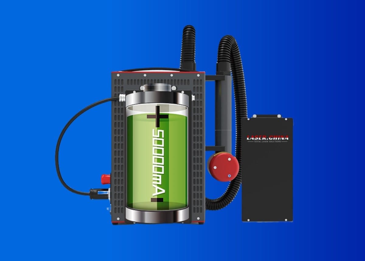
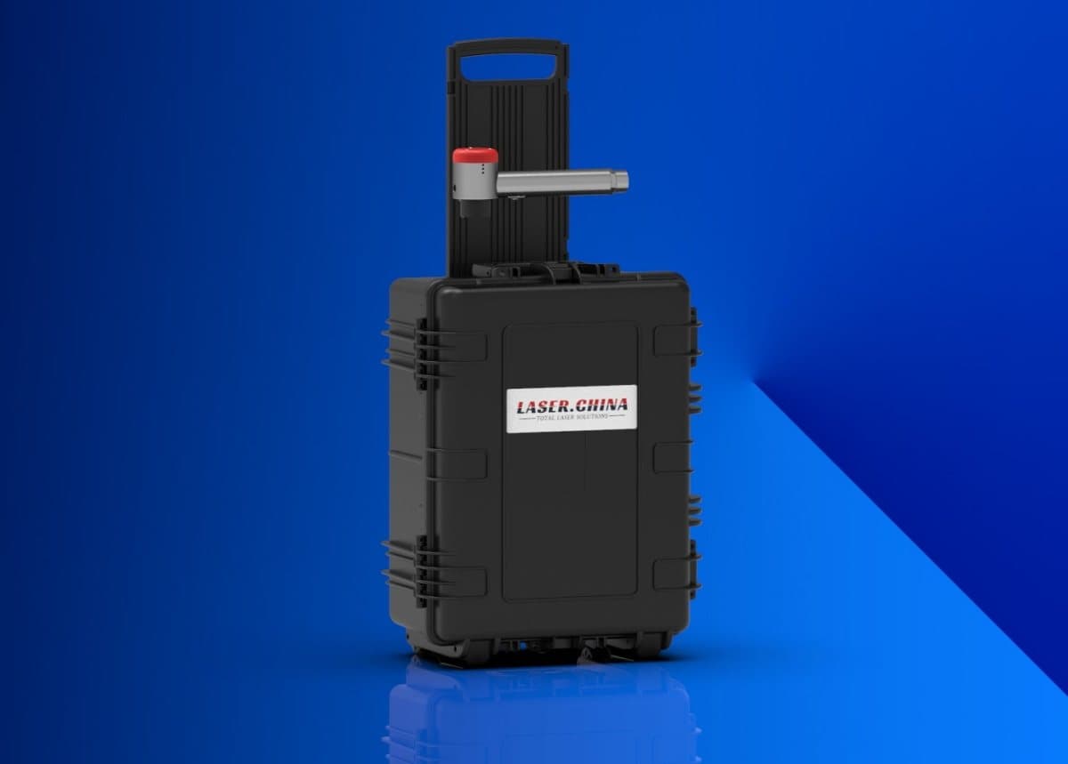
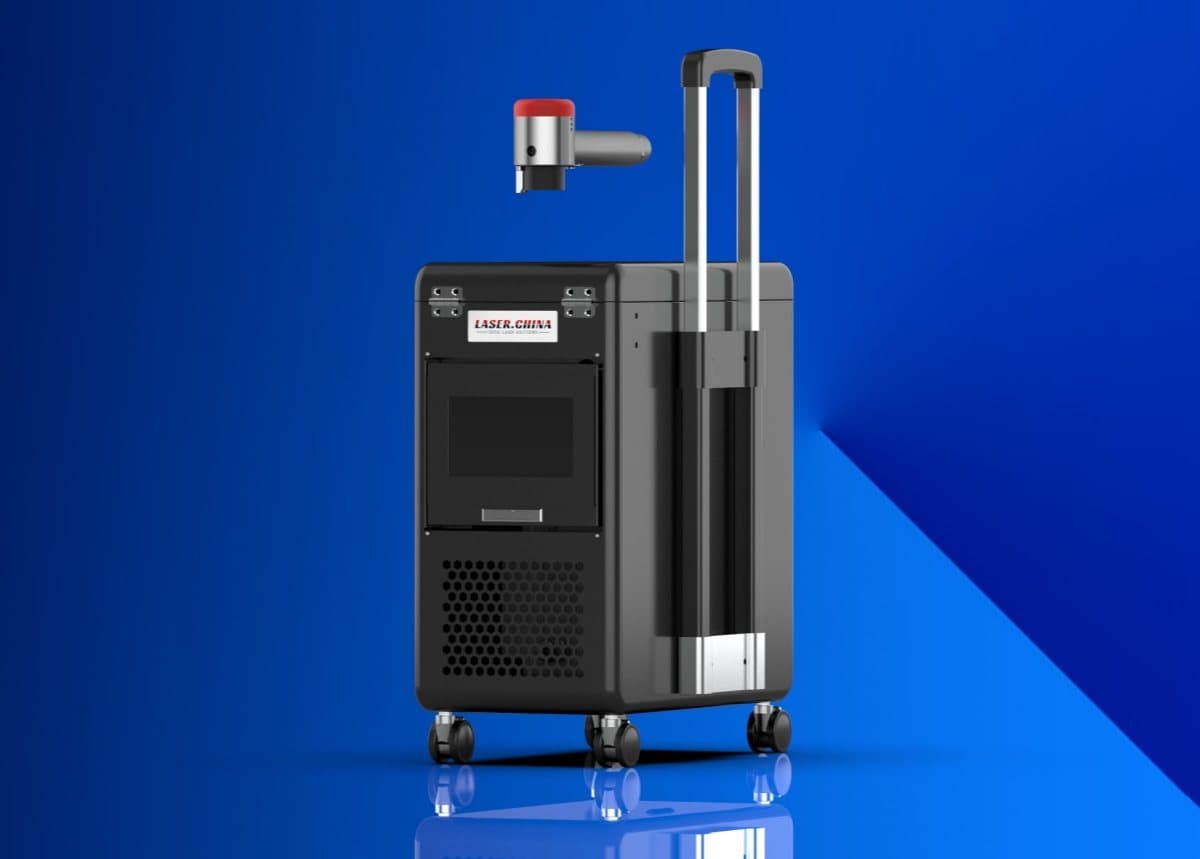
On format, a bench-top or fixture-mounted setup with air cooling is typical for station work. A portable unit is useful for rework and for large assemblies. Fume extraction should sit close to the work.
Practical notes
Think about where the laser sits in the flow. Because the oxide re-forms in air, cleaning right before soldering or welding gives the best result, so a station next to the joining step usually beats a separate cleaning area.
Also decide how you will inspect. Joint tests are the real measure, but a simple incoming check, such as wetting on a test coupon, can tell you each day whether the setting still works.
Set up the work area before the first pulse. Fix the part so it cannot move, route the cable and extraction hose clear of the operator, and agree the stop procedure. Keep the lens clean, because a dirty protective lens lowers delivered energy and makes results drift. These small habits cost minutes and prevent most surprises on the first day of real production.
What to test first
Step 1
Take parts from the actual lot, with the same plating and the same oxide condition, plus a few clean reference parts.
Step 2
Clean a few at the lowest setting and inspect under magnification. Check for plating wear, discolouration and any change in edge or dimension.
Step 3
Measure what matters: contact resistance, solder wetting, weld strength or a pull or shear test, depending on the joint.
Step 4
Raise energy in small steps until the joint results are consistent, and note the margin between that setting and the one that begins to mark the plating.
Step 5
Define the time window between cleaning and joining, because oxide re-forms in air.
Limits: when not to use a laser
- Where the oxide is thick or the plating is thin, there may be no safe margin between clean and damaged. Test, and be ready to choose another method.
- Very small features or deep recesses may be shaded from the beam.
- Polished or highly reflective surfaces reflect much of the beam and can need different settings, and reflections need care.
- Static-sensitive and thermally sensitive components should be treated per your own process rules. The laser does not remove the need for ESD control.
- This is a Class 4 laser. Use 1064 nm eyewear, screen the station and use extraction.
Next step
See related sectors on the industries page, or send a sample lot and we will run a remote test on your parts.